SegelFlieger
-
Posts
45 -
Joined
-
Last visited
-
Days Won
3
About SegelFlieger

Recent Profile Visitors
2,470 profile views


SegelFlieger's Achievements
Member (2/7)
72
Reputation
-

LPG 120x90# quad set by Kite Forge (October 10, 2022)
SegelFlieger replied to John Barresi's topic in Current Drawings
Thank you! I'll put them to good use! -
3D Printing For Kite Making and Customization
SegelFlieger replied to SegelFlieger's topic in Adjustments and Modifications
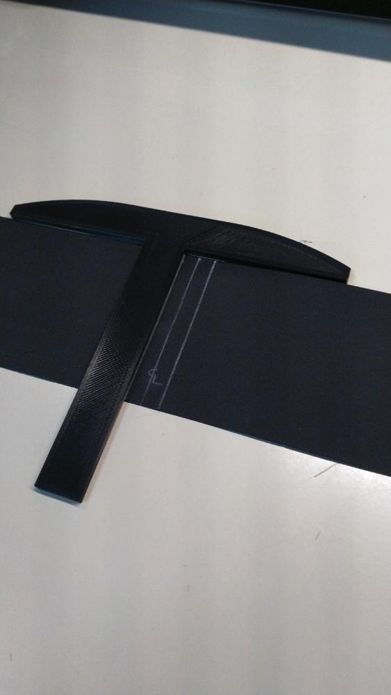
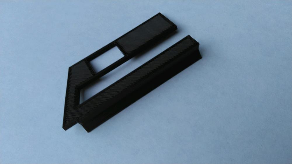
Here is a handy tool. If you are building your own kites you will soon notice that you spend a lot of time drawing perpendicular lines on Dacron Tape or Fabric. Measuring, marking, and using a straight edge to draw a straight line is very time consuming and not very accurate. Here is a 3D model of a Mini-TSquare designed specifically for drawing perpendicular lines on Dacron Tape. The lines will be quick to draw and perfect every time. -SF MiniTSquareV2_01.stl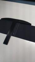
-
3D Printing For Kite Making and Customization
SegelFlieger replied to SegelFlieger's topic in Adjustments and Modifications
Don, That's a great story! And thanks for including the link to thingiverse; others in this forum should explore it to see what else a 3D printer might be able to accomplish for you. There are TONS of models that can be printed if you don't want to invent them yourself; unfortunately, not many models are kite related (*yet*) but there are a few. As our forum conversations go, we are discussing the use of 3D technology for kite parts and modifications but you make an excellent point: You shouldn't consider that this is the only purpose your printer will serve. Rather, consider it like an investment for the next power-tool that you want to buy for a DIY project and it will end up becoming useful for many other things as well; like that obsolete plastic part from Sears for your dishwasher basket, akin to the "clutch interlock safety switch bumper". And regarding machining tools vs 3D printing, I often think, and am still in awe, about the differences in how a part is made using each. While machining you create a part by removing material and there is, of course, waste; stock material cut to size and discarding what you can't use, removing the remaining material until you have the part you wanted. When 3D printing you create a part by "adding" material and there is very little waste (sometimes you need supports which are discarded). an aside: As an example of machining waste: when making an airplane wing frame for a commercial aircraft, ~90% of the Aluminum material is removed and discarded. -Segel -
3D Printing For Kite Making and Customization
SegelFlieger replied to SegelFlieger's topic in Adjustments and Modifications
Reply to Frob, Great points about concerns regarding strength and mechanical properties of a 3D printed part. There are many adjustments that can be made during the "Slicing" process that can make your component weak or strong, independent of the material you are printing. Getting that right can make all the difference. The "litmus test" is to stress test the part after it has been made. For connectors I use drill bits to fit the connectors at their differing angles and pull very hard until I break them. When I can barely break them or not break them at all I call my part good. One concern I have with PLA+ is high ambient heat. I have not put my printed parts in the trunk of my car for long periods. I will experiment with that and let you know how that turns out. It's supposed to by 100+ tomorrow in Spokane. I will put a PLA+ Rev End Cap in the worst possible place of my car and let you know how it turns out. -Segel -
3D Printing For Kite Making and Customization
SegelFlieger replied to SegelFlieger's topic in Adjustments and Modifications
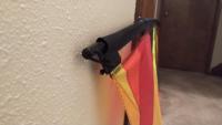
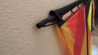
3D Printing Example Here is an example of a problem that I solved making a part with my 3D printer. I’ve been in the process of getting ready to go to Long BeachWA the week of August 17th to enjoy some time away with my wife and some good wind and hopefully some good company of other kite flyers. Anyway, I had a long list of things to repair and check to get ready. After I repaired my kite and assembled it, I was bothered by one thing I never liked about the Rev LE; the rods on the ends droop below the LE pocket and don’t support it. This isn’t ideal in low wind. One morning I was walking and thinking and this idea came to my head. An hour later it was a reality. -Segel
-
3D Printing For Kite Making and Customization
SegelFlieger replied to SegelFlieger's topic in Adjustments and Modifications
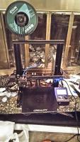
3D Printing Workflow This post goes out to Riffclown, wanting to make parts that don’t exist... Note: I have intentionally not included links to the software products that I mentioned because versions and websites change frequently. Instead just Google the bold-faced product names and you will find a current link. It sounds like many of you are experienced with the process of 3D printing, but for those of you who are not and are considering it I would like to try and explain, as simply as possible, what you need to do to make a 3D print. I tend to be slightly verbose in my explanations but don’t let a lot of text make it seem like this is really hard to do. (simple but verbose J) Purchase a 3D printer. There are many on the market but I have given an example of the Creality Ender 3 Pro which works very well for me. Choose what you think will work best for your needs. Have an idea ready. Get a piece of paper and sketch something that you intend to make. You may be replicating, improving, or modifying an existing design that you physically have. In that case you will want to have a “caliper” that you can measure your existing part; preferably digital, get one that has both standard and metric units. Sketch it with dimensions that you will need to build it; it doesn’t have to be perfect or to scale, just accurate enough that you can draw the 3D Model which is the next step. Create a 3D Model. This requires a computer and software to create the model. There are some excellent options that are FREE available for making mechanical parts. I should say beforehand that learning how to use the software requires a large investment of time but it is worth it. Because of this you may want to consider the choice that you make. Fusion360 by AutoDesk (the AutoCAD folks) is an awesome package and will do way more than you would ever learn how to do for your designs; it is free for hobbyists and startups but should you ever decide to sell anything you are designing then you will have to pay a subscription. DesignSpark Mechanical on the other hand is also a very capable 3D design software package and is FREE for both personal and commercial use. Learn to convert your Sketches into 3D Models with this type of software. Save your 3D Models as an .STL file for the next step. Once you have a 3D Model (.STL) file, then you will need to prepare it to print. This is done using what is called “Slicing” software. This is software that you tell it beforehand what your printer model is and what material you are printing and then use it to create a file that your Specific printer can understand to print it. This is called a .gcode file. This file format goes way back to the origins of CNC machining. I use Ultimaker Cura which is also FREE and probably one of the most common slicing software applications out there. Within the Slicing Software there will be several settings that you can configure for the print. A few are very important for creating the result that you intend to get. I will not elaborate on these now but a few are rather important to make strong parts. To summarize this step: you create a .gcode file your printer can understand to make the print. Unlike a paper printer that you are used to, you don’t usually have the 3D printer connected to your computer; prints take from 5 minutes to 1 ½ days depending on the size and resolution. Instead you usually copy the .gcode file to a memory card and insert it into the printer. There are then steps for your specific printer to preheat it. You must also level the bed of your printer before printing. You then select the .gcode file you created from your printer and tell it to print. So those were a lot of words, and it seems like a daunting process. But once you become familiar with the quirky details required for your setup, you will become creative, I guarantee it. Expect frustration in the beginning, but you will be rewarded with a tool that you never imagined was possible once you are friends with it. -Segel -
3D Printing For Kite Making and Customization
SegelFlieger replied to SegelFlieger's topic in Adjustments and Modifications
Hello Don Fibonacci, The most common material that is the easiest to print is PLA. I use a variant designated as PLA+ and have been using the eSun brand exclusively with excellent results; this brand is what our Public Library uses city-wide and was recommended to me, and I can see why. PLA+ varies by manufacturer. Each have tried to improve the mechanical properties of PLA and eSun has done a very consistent job of it. In following posts I plan to describe my experience with materials. ABS is very difficult to print with an open-frame printer. ABS requires very tight ambient temperature control for the object you are printing due to the high glass-transition temperature of the polymer; warping on medium to large parts is unavoidable without a temperature controlled enclosure. I am guessing that you might be able to resolve your "coarse" print issues by adjusting some settings in your slicing software. I rarely sand my prints unless I am removing printed "supports" which I will also expand on later. I hope this is helpful and I'm glad you are interested in experimenting! -Segel -
3D Printing For Kite Making and Customization
SegelFlieger replied to SegelFlieger's topic in Adjustments and Modifications
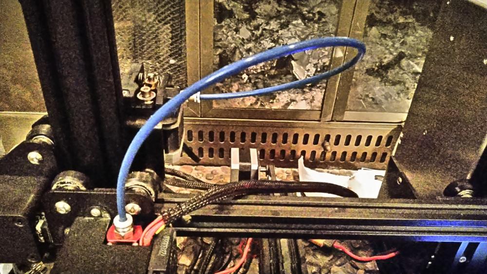
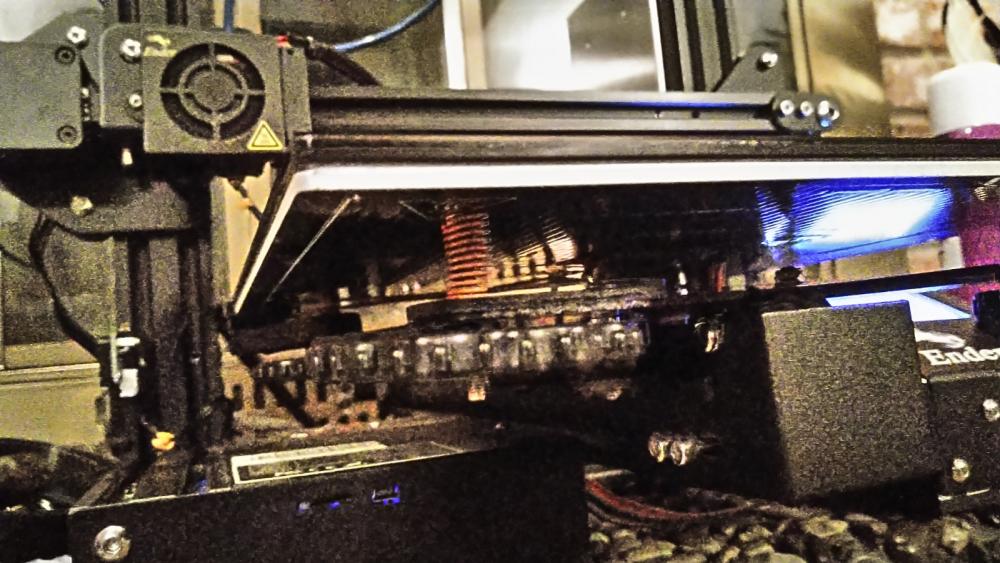
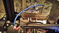
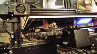
Great! I’m ecstatic that there is an interest in the subject. I will start with my personal discovery of this technology. Almost a year ago today I was trying to create some rather complex kite-flying related parts and planned on making them with my available shop tools. A friend of mine suggested that I consider 3D printing them; note that he knew absolutely nothing about the technology but had heard about it. I shrugged it off remembering that my children’s High School had purchased a multi-thousand dollar printer and kept it locked in a room so the kids couldn’t break it. Too much $$ for what I’m wanting to do I said. Then, my friend and his wife went to a local Library technology class introducing 3D printing and reported that I should really look into this. I then did my first Google search on the subject and found out that this is really much reachable for the consumer these days. I found that you could purchase a *very* capable 3D printer for ~$250 or less which is not much more than a regular laser printer might cost. Having been stung with the price of Ink Cartridges and Toner costs to operate a printer, I was bracing myself for what it will cost to feed a 3D printer... $16 - $25 for a Kg of filament! This will probably mean nothing to those of you who haven’t explored this but a Kg of filament lasts quite a long time! After doing much research I found that the Creality Ender 3 Pro was the place to start. There are many printers on the market but this one received great reviews for features that higher priced models had such as a heated bed, .1mm resolution, and the ability to modify it. Which I did. I have made the following modifications, each cost ~$15 each but were well worth the cost: 1. Replaced the magnetic bed with a glass bed; makes removing parts much easier 2. Replaced the bed springs with actual compression die springs; less bed leveling required 3. Replaced the original Bowden tubing with Capricorn tubing which has tighter tolerances and is slicker; improves Filament Retraction performance. I have attached some pictures of each of these. Note that the Ender 3 Pro requires a moderate amount of assembly and it helps to be mechanically inclined. Following comments on this post I plan to follow-up with the work-flow required to use the printer. -Segel
-
I would like to propose a new topic relating to the use of 3D Printing technology to create parts for building and customizing kites. I have almost a year of experience with this technology, using it every day, and would like to share what I have learned with those of you who are interested in the subject. I am an engineer by profession and finding this new tool has been the realization of a dream of a lifetime... If I can sketch an idea on paper and then create a 3D model of it with software then I can hold a physical example of my idea in my hand after printing it. Many ideas can be used as functional parts rather than just prototypes. Surprisingly, the technology is rather affordable for the consumer these days. But there is a moderate degree of skill that you will need to have to design and print your own parts. Printing parts that others have designed is less complicated but also requires some computer skill and skill in using your particular printer. If it is agreed that this is an interesting topic, then please reply and I will give an introduction to my setup and workflow and some examples of parts that can be made. I’m looking forward to your replies. I am very enthusiastic about the subject and hope that your input will also help me gain knowledge. Regards, Segel
-
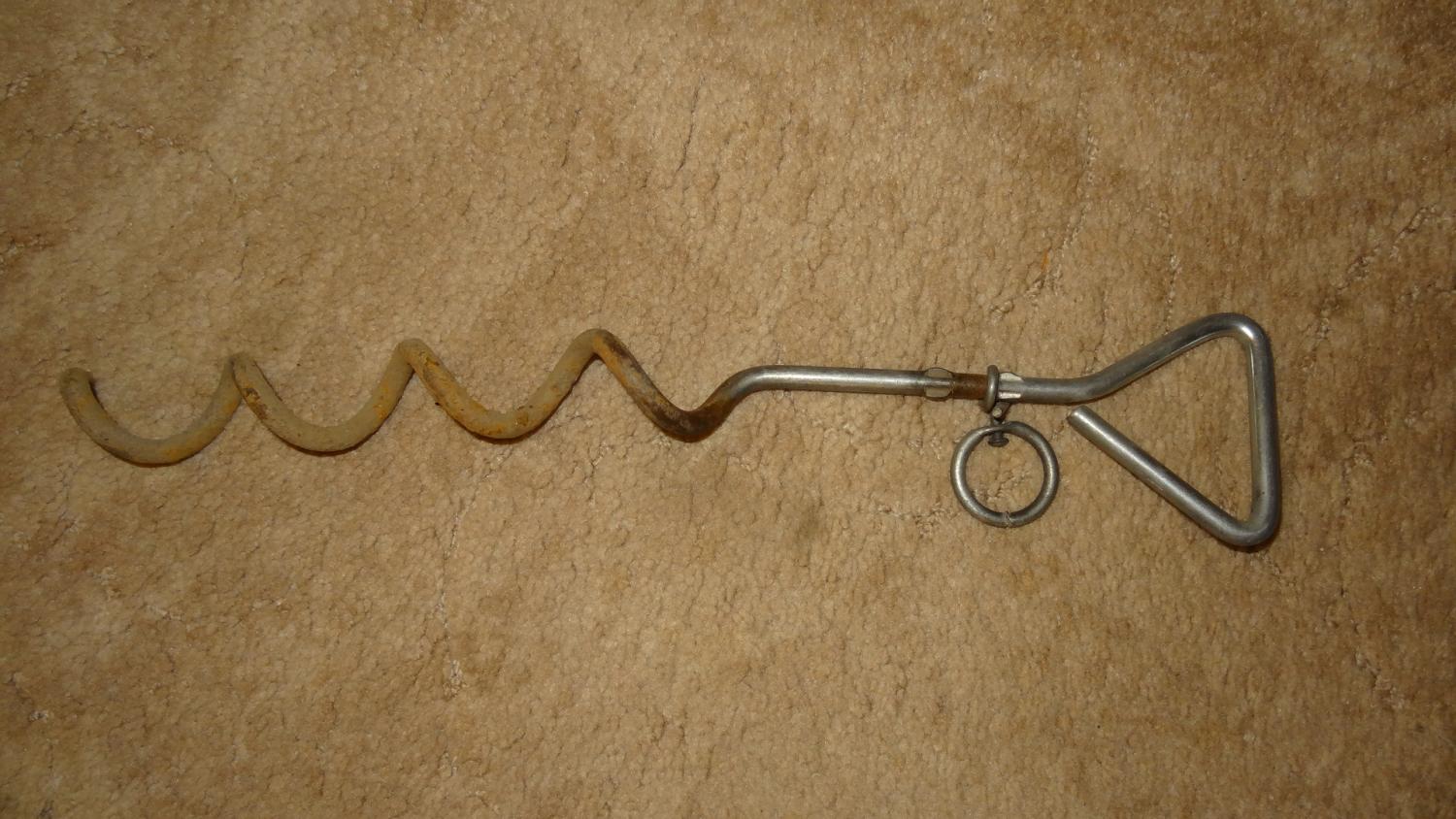
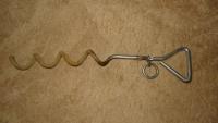
I am most of the way there! Thanks to my beloved Kaela, a Keeshond, who left this to me when she passed several years ago along with many fond memories. I throw nothing away. 😥 😀 Since I posted my question I have discovered multiple posts regarding Dog Staking both on KiteLife as well as an interview with John on "kite-and-friends" and have seen the fabulous rig that John designed as well as its evolution. Thanks for the pictures and the video from Jeremy that were recently posted. Very inspiring! link to interview here: https://www.kite-and-friends.de/international/groundstake-kiting-with-john-barresi/ In the absence of being able to purchase a very rare piece of gear, I am “In Deep” with ideas to make a rig of my own, compelled to try the Dog Stake Experience! If I am successful I will share my design. I am trying to keep my project in reach of those who have access to common household machining tools, a drill press is the most advanced tool. And I am trying to keep the material cost below $100. One of my primary goals is to try this without causing damage to my lines. And of course, make something that works. It may not be pretty though. But at 60' and your kite flying right with you, you may just forget about how it looks... or forget about that it is there altogether. Thank you both for responding to my inquiry and I may have a few more questions as I proceed. Best Regards, Segel
-
I am interested in experimenting with Dog Stake Quadline Flying. What is the currently preferred rig for this? I have read an informative post from Paul LaMasters from several years ago with a design plan posted but the part numbers no longer seem available. I have also been looking for diamond polished SiC fishing guides that might be similar to what was used in that design but I am coming up empty. What do those of you who fly Dog Stake use? Segel
-
Here is a blog I posted a while back regarding dynamic testing of spars along with weights and deflection information:
-
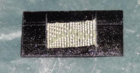
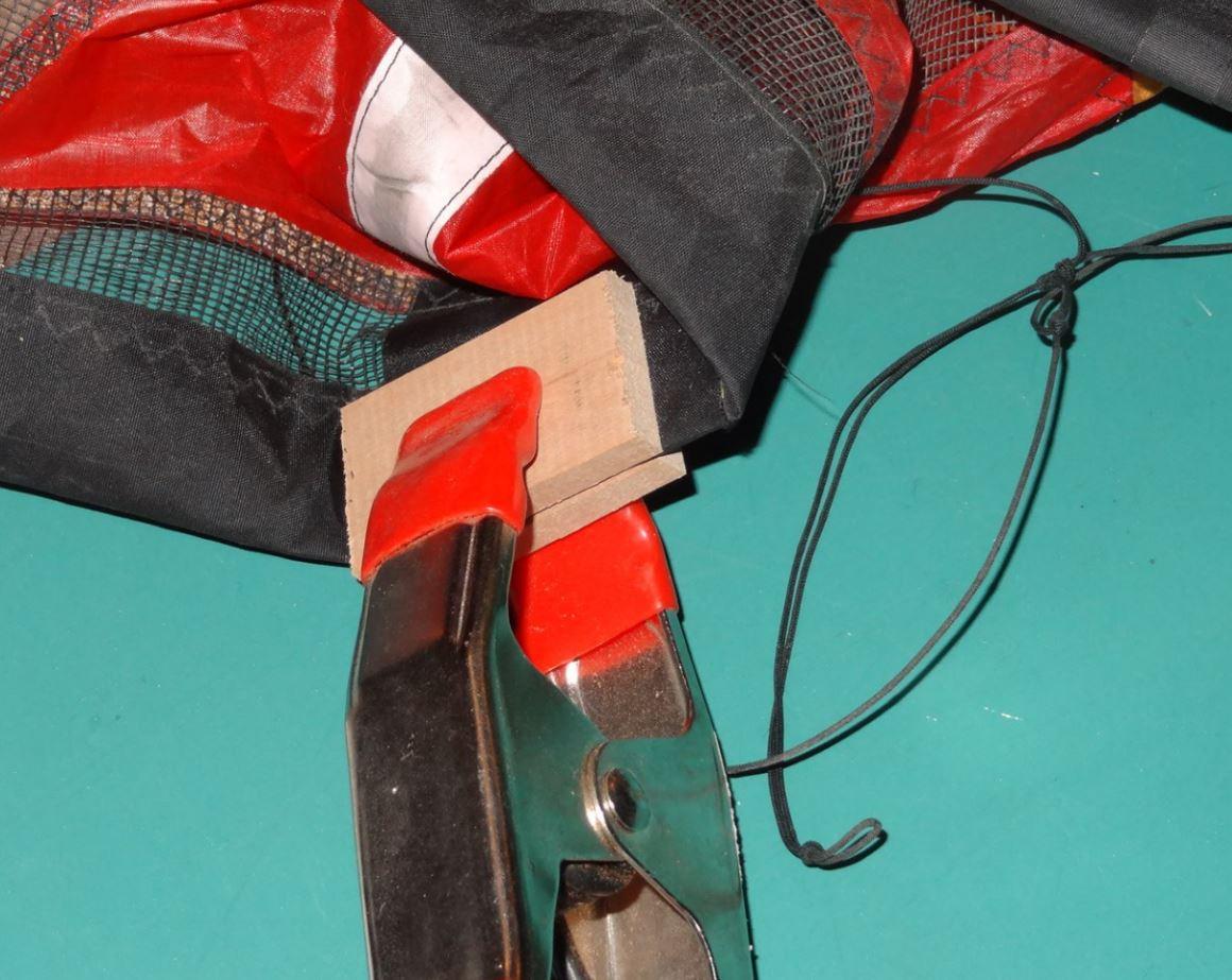
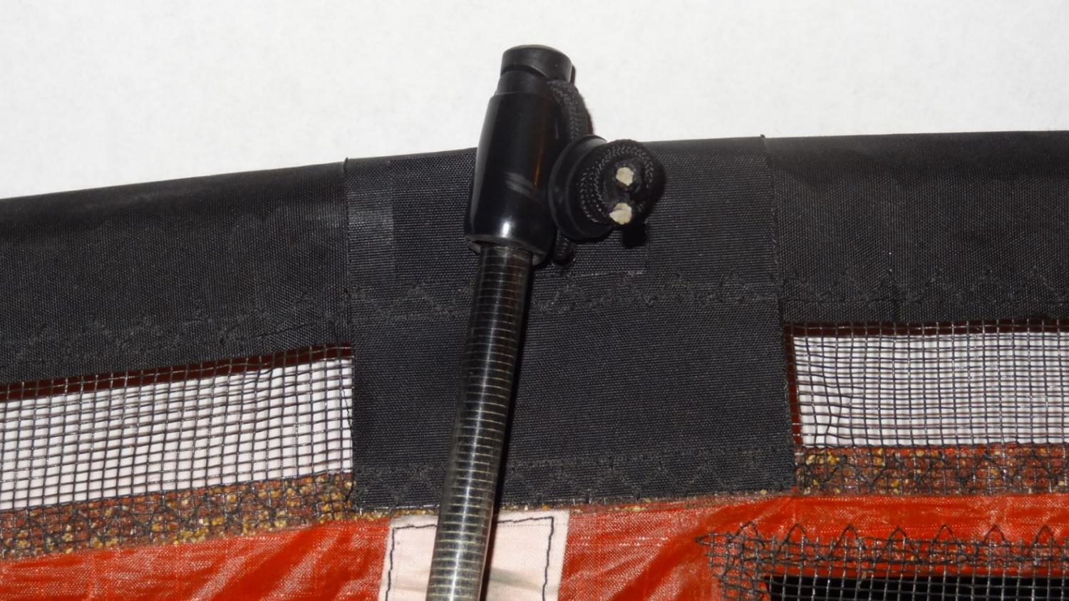
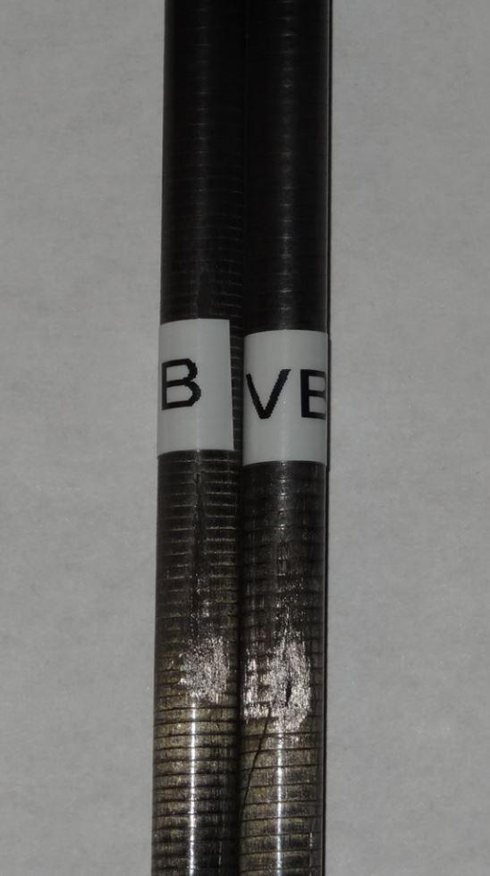
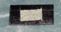
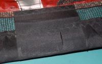
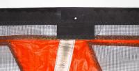
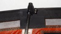
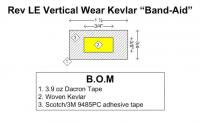
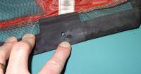
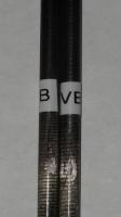
Abrasion is a common problem with the Rev LE Vertical Tabs caused by the vertical spars or end-caps rubbing against the Dacron tabs and eventually coming in direct contact with the LE spar. The B-Pro series kites have a piece of Kevlar sewn internally to this tab which prevents this problem. But what do you do if your kite suffers damage and does not have this nice pro feature? Introducing the Kevlar Band-Aid... It is a simple idea and is probably self-explanatory but I thought I would share how I repaired the damage to my kite in case it might help you. Here is the damage that occurred to my kite: To repair this damage I made a “Kevlar Band-Aid” from Dacron Tape, woven Kevlar, and a strong 3M adhesive tape. Here is the design followed by a picture of the Band-Aid: Note that the adhesive tape that I used is very strong and you only get one chance to apply it to anything, hence the Kevlar being slightly askew. Avoid touching it with your fingers. Apply the Band-Aid to the damaged area and clamp it for several hours. After the Band-Aid has been applied you will probably need to recreate the hole for the vertical end-cap shock-cord. I use a soldering iron or wood burning tool to do this... Applied Band-Aid and recreated hole Here is the completed repair: Your vertical spars probably have suffered some damage if this has happened to you. I labeled the damaged ends of my spars as “VB” (Vertical Bottom) to insure that I use these spars only for the verticals and place the worn ends at the bottom. From the picture it appears that there is a crack in one of the spars but this seems to be a crack in the “clear coat” that was applied to the spars. It would certainly be a good idea to have spares should a worn spar fail while you are in the field. I hope you find this useful. S.F.

-
The information from these posts inspired me with ideas to create my own Nail Board. I shared my experience recently in the form of an "instructional" blog as I felt it was too lengthy to post as a reply to this topic. If you are interested in reading it, here is the link: I hope you find it useful. SF
-
I was inspired by the information shared in recent posts regarding the existence of something called a "Nail Board" to help tie accurate "Knot Systems" such as bridles, leader lines for handles and potentially other applications. I decided that what I am about to share is too lengthy for a forum post so I have posted this as a blog instead. I hope you find it useful. SF Nail Board Instructions for Knot Tying A Nail Board consists of a “flat board” with physical markers defining the spacing between knots tied in a line for a specific purpose. “Bridles” and “Leader Lines for Handles” are good examples but there may be other line applications that a Nail Board can be used for. Summary: A Nail Board serves two purposes that provide an advantage to using a tape measure or rule for tying lines with knots that require precise and symmetric spacing: 1. The location of each knot can be consistently and accurately marked. 2. The line material can be pulled under light tension when making the marks using the physical markers. This allows the spacing of the knots to remain proportional when stretched during wind-loaded flying conditions. What a Nail Board does not do for you: You can’t tie single or multiple loops from the dimensions on the board; the dimensions on the board are “final” dimensions of the “knot system” you are tying. Prior to tying looped knots you must determine the length of line that is required to tie the loops, or other knots, to fit the final dimensions of the physical markers on the Nail Board. Details: Knot Tying vs Knot Marking. The process of tying the knots is separate from the marking of their location. Each type of line material has a specific diameter and each knot and type of knot takes a specific length of line to tie. This must be determined beforehand. The actual line required to tie a knot system is defined as: Line spacing defined between the knots + “length to tie” for all knots in the system. Calculating the length of your line to tie a loop knot (“Length to Tie”): Mark a 12” length of the line with which you will be tying a knot. Call this “D1” Note: in the picture I used blue tape as a mark only for the purpose of illustration. I use a white “cloth marking pencil” to make my marks which does not show up well in a photograph. Tape is not a good material to use for marks since it can slip on the line while tying. Tie the specific knot that you will be tying. I have used an overhand knot for this example to form a loop. The marks that you previously made should be behind the knot by ~1”. The marks should match each other below the knot. Make sure that the knot is “Well Formed”. All lays are parallel with each other as the knot is formed; no crossing between the lays. Pull the knot taught with force after tying; I use my forceps in the top of the loop and pull very hard on the opposite end. Now measure the distance from your marks to the top of the loop. Call it “D2” Length to Tie = D1 – 2 x D2 . this will be the “Length to Tie” for this line and this loop knot. The length to tie a loop per knot for my material is 1 1/8” believe it or knot (100# bridle line) Here is an example: In this example there are two loops. The total length of the knot system is 3” (2 ¼” + ¾”). The length of line required without knot consideration is 6”. There are two knots in this loop system, one at the bottom and one towards the top, which will take 1 1/8” each for my line material. The total length of line to tie both knots in this system is 6” + 1 1/8” + 1 1/8” = 8 1/4”. For a single knot (not a loop) in a line the “Length to Tie” is simply: Length to Tie = D1 –D2 after you have performed the same experiment with a single knot in one line. How to use the “Length to Tie” The “Length to Tie” must be added to the line dimensions when you are tying your knots. After they are tied, they should fit back on the Nail Board and be under slight tension. Conclusion: Following these procedures and using a Nail Board should result in very accurate knot placement for your projects. When tying more than one identical knot systems, they will end up being perfectly symmetric. Materials and tools required to make "my" board are: #18 x 3/4” wire brads. 36” x 5 ½ x 3/4” Pine Board (premium grade, flat, actual measured dimensions shown) Drill press with depth stop capability (not required but adds precision and protects the drill bit). 3/64” drill bit (available for Dremel tools or other sources) Long Straight edge rule 4 ft (for drawing straight lines on the wood) Tape measure for measurements of marker placements.